
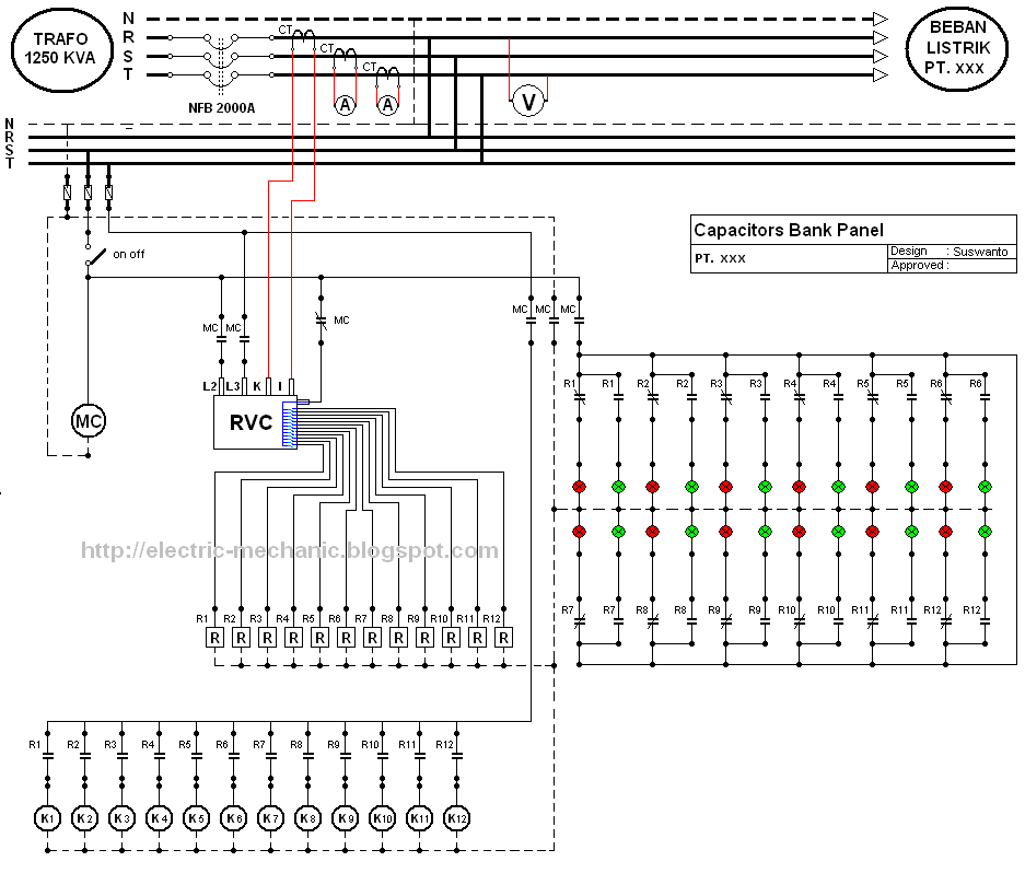
Wiring Diagram Komplit Panel Kapasitor Bank YouTube
Excellent. The aim of project called „Reactive power compensation panel" was to design capacitor bank with rated power of 200kVar and rated voltage of 400V adapted for operation with mains, where higher order harmonics are present. The capacitor bank was to be power capacitor based with automatic control by power factor regulator.
wiring diagram kapasitor bank
These units are mainly connected in the form of a star/delta connection to make a whole three-phase capacitor bank. At present most frequently available capacitor units are 1-phase type whereas 3-phase capacitor units are rarely manufactured. There are three types of capacitor banks which are discussed below. Internally Fused Externally Fused

Wiring Kapasitor Bank 3 Phase Tugas Sekolah
Wiring kapasitor bank 3 phase terdiri dari beberapa komponen seperti kontaktor, breaker, relay, dan fuse. Pada pengkabelan kapasitor bank, harus diperhatikan arus listrik yang melewatinya. Kapasitor bank harus terhubung dengan rangkaian listrik yang mempunyai arus listrik yang stabil dan tidak berlebihan. Hal ini dilakukan untuk menghindari.
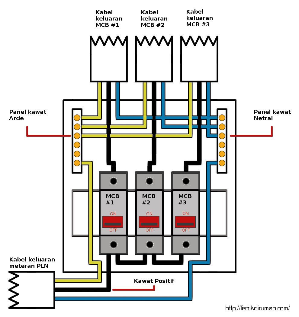
Diagram Instalasi Listrik 3 Phase Skema Diagram
Figure 5 - Double star connections, neutral earthed capacitor bank. Go back to Content Table ↑. 1.5 H connection. H connection can be used for delta or star single-phase or three-phase connections. The schematics below represents a branch between two phases or between phase and neutral. This type of wiring is intended for high power HV.
Ini Dia 5 Fungsi Kapasitor Bank yang Wajib Kamu Tau
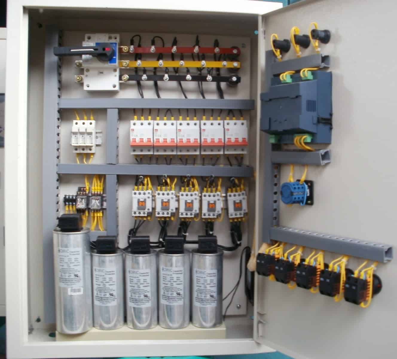
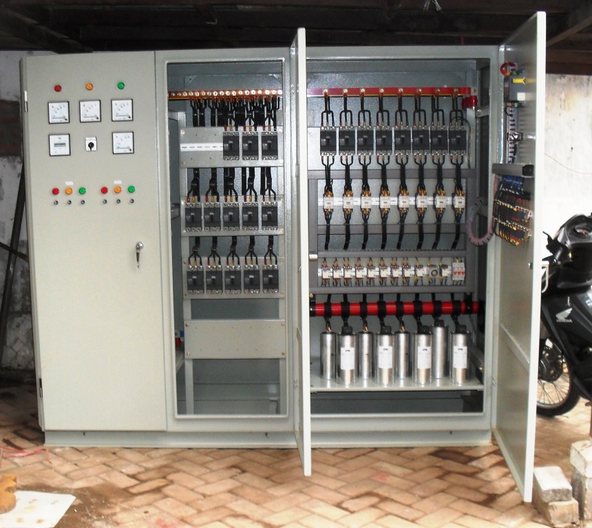
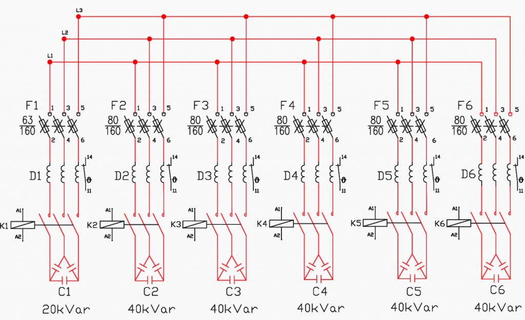
Capacitor Bank. Gambar. SAMUDRA PANEL. Phone : 031 898 5009 / 081333081473. Harmonic polution rate; 15 - 25 % (THDU) total Harmonic Distortion of Voltage; Power per Step 12; Step Step Compotition 3 Phase 50 kVAR 450 Volt +3 Phase 40 kVAR 450 Volt ; Location of Connection Bottom; Controller Type JKF8 Series;. Current Transformer Wiring.

TIPS CARA PEMASANGAN CAPASITOR BANK PADA INSTALASI LISTRIK 3 PHASE
The three phase capacitor bank wiring diagram includes several electrical principles that are important to understand. These include the principle of conservation of energy, which states that energy is neither created nor destroyed, but can be converted from one form to another. Another important principle is Ohm's law, which states that.

Wiring Kapasitor Bank PDF
kVAR Rating of the Capacitor Bank The total kVAR for the capacitor bank shall be specified. Since this is typically a three-phase application and the most common single-phase capacitor unit sizes are 50 kVAR, 100 kVAR, 200, kVAR 400 kVAR, 500 kVAR, and 600 kVAR the most commonly specified total capacitor bank sizes are: 150 kVAR 900 kVAR 1800 kVAR

Wiring Kapasitor Bank 3 Phase Tugas Sekolah
Brett Martin July 30, 2018 Assortment of 3 phase capacitor bank wiring diagram you are able to download for free. Please download these 3 phase capacitor bank wiring diagram by using the download button, or right click selected image, then use Save Image menu. What is a Wiring Diagram?

Three Phase Wiring Diagram For House
The wiring diagram panel kapasitor bank is a tool that provides an organized, graphical visual representation of the wiring system of the home or business. It can help users quickly and easily identify where connections need to be made and where wiring needs to be re-routed or replaced. When choosing a wiring diagram panel kapasitor bank, it is.
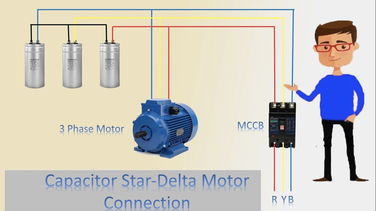
3 Phase Motor With Capacitor Wiring Diagram inspirex
Solution #1 (Table Method) We have already calculated the required Capacity of Capacitor in kVAR, so we can easily convert it into Farads by using this simple formula. Required Capacity of Capacitor in Farads/Microfarads. C = kVAR / (2π x f x V2) in Farad. C = kVAR x 109 / (2π x f x V2) in Microfarad. Putting the Values in the above formula.

Apfc Panel 3 Phase Capacitor Bank Wiring Diagram Electronic Diagram
Kapasitor bank ini digunakan untuk kompensasi daya reaktif dan koreksi faktor daya di gardu listrik. Daya Reaktif Kapasitor Bank (kVAR) Daya yang mengalir bolak-balik atau bergerak dua arah, tetapi tidak melakukan kerja apa pun dalam rangkaian listrik disebut daya reaktif.
[DIAGRAM] Wiring Diagram Panel Capacitor Bank
Most homes have electrical systems that power the lights, appliances and other devices. But managing electricity distribution safely and efficiently requires more than just wiring up a wall socket and plugging in an appliance. To ensure safe and reliable electricity transmission, it's important to understand 3 phase capacitor bank wiring diagrams, which provide valuable insight into the.
Wiring Diagram Capacitor Bank Wiring Diagram 06E
A capacitor is an electronic device that stores electrical energy in an electric field by accumulating electric charges on two closely spaced surfaces that are insulated from each other. It is a passive electronic component with two terminals.. The effect of a capacitor is known as capacitance.While some capacitance exists between any two electrical conductors in proximity in a circuit, a.
wiring diagram panel kapasitor bank
A capacitor bank wiring diagram is a schematic representation of the connections between the components of a capacitor bank. It shows which components are connected to each other, and it also indicates the flow of current through the components.
3 Phase Capacitor Bank Wiring Diagram Greenist
HVAC 3-PHASE CAPACITOR BANKS Designing capacitor banks starts with basic information collection with respect to facility and immediate utility network characteristics. Network rated voltage, operating voltage, frequency, and short circuit availability are necessary for proper capacitor bank design.
The basics of capacitor banks protection EEP
The wiring diagram capacitor bank is an integral part of a power system. It is the basic infrastructure of power transmission and distribution networks. The capacitor banks are connected between two points of a circuit, usually the high voltage conductors, in order to reduce the total power losses and improve the efficiency of the power system.